Optical Kerr Gate
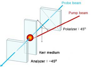
The optical-field-induced birefringence can change the polarization of a beam propating in the medium. Conversely, measurements of the change of the beam polarization should allow us to deduce values of the induced birefringence.
The optical Kerr effect, which usually refers to the phenomenon of linear birefringence induced by a linearly polarized optical field. We assume an isotropic medium here for for simplicity. With a pump beam at w and a probe beam at w', the third-order polarization at w' takes the form
- P(3)l=∑j[X(3)1122(w'=w'+w-w)El(w')Ej(w)E*j(w)
- +[X(3)1212(w'=w'+w-w)Ej(w')El(w)E*j(w)
- +[X(3)1221(w'=w'+w-w)Ej(w')Ej(w)E*l(w)]
- +[X(3)1221(w'=w'+w-w)Ej(w')Ej(w)E*l(w)]
If the two beams are parallel and their polarizations are linear but at 45o with respect to each other, then with the pump field E(w) along x propagating along z, one finds
- P(3)x=(X(3)1122+X(3)1212+X(3)1221)Ex(w')E(w)E*(w')
- P(3)y=X(3)1122Ey(w')E(w)E*(w')
The field-induced anisotropy in the susceptibility is therefore given by
- δ χ(w')=δχ xx - δχ yy
- =( X(3)1212 + X(3)12221 ) |E(w)|2
- =( X(3)1212 + X(3)12221 ) |E(w)|2
or the induced linear birefringence given by
- δ n l (w') =( 2 π / n ) δ χ (w')
- =( 2 π / n ) (X(3)1212 + X(3)12221 ) |E(w)|2
- =( 2 π / n ) (X(3)1212 + X(3)12221 ) |E(w)|2
Then, in propagating through a medium of length l, the x and y components of the probe field experience a relative phase difference [1]
- δ Φ = (w' /c ) δ n l l
Since the advent of stable ultrafast laser source the optically heterodyne detected optical Kerr-effect (OHD-OKE) has become established as one of the leading experimental routes to uncovering intermolecular mode liquids.
More recently it has proved a valuable probe of dynamics in complex or heterogeneous fluids, including biopolymers[2], confined liquids[3], ionic liquid[4,5], and microemulsions[6].
Experimental setup
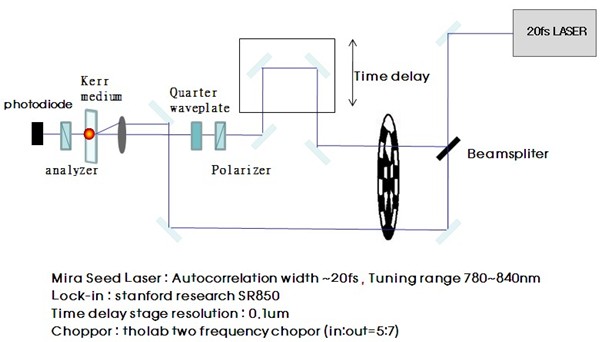
The center wavelength of the tataninum sapphire laser was about 800nm and the repatation frequency was 76MHz. The output power of the laser was about 250mW.
The laser beam was first passed through a polarizer, before being incident on a beam splitter, yielding two separate in the intensity ratio of 95:5, the pump and probe beams.
The time delay between pump and probe beams was varied by translating a resolution mechanical stage (resolution 6.67fs/step) that was inserted in the optical path of the pump beam.
Both the transmitted pump and probe beams pass through different rings of a choppor wheel that modulates them at a 5:7 frequency ratio.
The probe passed through a Glane-Laser polarizer the polarization +45o from horizontal,and then through a quarter-wave plate before the focusing lens.
To achieve heterodyne detection, an out of phase local oscillator was introduced by rotating the input polarizer by either +1o or -1o away from the homodyne orientation.
The pump and probe beams were focused into a 1mm path length sample cell with a 60mm focal length lens.
The pump beam was blocked while the probe beam was sent through a second Glane-Laser polarizer, which set at the polarization of -45o.
The kerr signal was detected by a amplified PIN photodiode and recorded by a lock-in amplifier
[1] Y. R. Shen, The Principles of Nonlinear Optics, Wiley Classics Library Edition Published 2003
[2] G. Giraud, J. Karolin, and K. Wynne, Biophys. J. 85,1903 (2003)
[3] B. J. Loughnane, R. A. Farrer, A. Scodinu, T. Reilly, J. T. Fourkas, J. Phys. Chem. B 104, 5421 (2000)
[4] H. Cang, J. Li, M. D. Fayer, J. Chem. Phys.119, 13017 (2003)
[5] H. Shirota, J. F. Wishart, E. W. Castner, J. Phys. Chem. B 111, 4819 (2007)
[6] N. T. Hunt, A. A. Jaye, A. Hellman, and S. R. Meech, J. Phys. Chem. B 108, 100 (2004)


